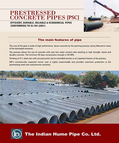
PRESTRESSED CONCRETE PIPE ( PSC )
IHP Introduced this pipe in the year 1956, in technical collaboration with Rocla Pipes, Australia. This product is the best choice for applications like:
- Pressure water transmission and distribution mains (Pumping & Gravity) for water supply, Drainage, Lift Irrigation Schemes.
- Re-circulation and cooling water pipe lines. For plants like Thermal Power, Chemical, Cement, Fertilizer, Paper, Refineries etc.
- Pressure water lines.
- Large diameter inverted siphon.
- Outfall Sewers.
- Gravity Sewer Systems.
- Storm water Drains.
- Culverts - Use of PSC in place of NP3, NP4 class pipes.
- Conveying any liquid, not corrosive to concrete including sea water and sewage force main.
The Design
The Basic Principle is to adopt wall thickness, circumferential and longitudinal Prestress to ensure freedom from tensile stresses in the core pipe under the most severe combination of sustained internal pressure and external loads likely to occur in service.
When transient loads such as surge or traffic are added to sustained loads, tensile stresses up to 30 kg/cm2 maximum may be permitted in concrete.
It is usual to divide pipelines in steps of Internal Pressure and design pipe for each section taking advantage of economy to be gained by tailoring design to suit actual needs without reducing safety. Where local high pressures or heavy external loads occur, pipes in these places can be strengthened without affecting cost of the remainder of the pipeline.
The following load components are taken into account.
- Mass of Pipe
- Bedding and Backfill
- Mass of water in pipe
- Construction traffic wheel loads
- Sustained Internal Pressure
- Highway traffic wheel loads
- Surge
Best economy and safety are achieved when pipe is designed for realistic in-service pressures and loads. The alternative method of designing pipes for a factory test, based on working pressure plus an arbitrary factor without regard to surge, earth or traffic loads is sometimes inadequate for low pressure. The same method can be wasteful for high pressure pipelines. Following determination of wall thickness and prestressing the next step is to calculate factory test pressure which will stress pipe as severely as it will be stressed in service taking into account mass of pipe and water and support condition. If a pressure, test is required on pipes after installation the value may be similarly calculated. The required ring strength of pipe can be readily established because internal pressure and external load conditions of the pipeline are known.
However, since loads causing longitudinal stresses are not known with certainty, it is assumed for design purposes that bedding is deficient and that pipe is a beam supported as its ends with backfill loads distributed evenly along the length of the pipe. This is conservative because installation specifications require bedding to be uniform along the length of pipe. Joint assembly design is related to clearances between joint surfaces , tolerance to pipe ends, rubber ring size, rubber hardness, creep of rubber on concrete. Blow-out resistance is produced for the most unfavorable combination of joint deflection and tolerance of pipe ends.
The Manufacturing Process
The process of Manufacturing IHP Prestressed Concrete Pipes consists of the following steps :
- Longitudinal Prestressing
- Batching & Mixing of concrete
- Spinning
- Demoulding
- Core Curing
- Winding
- Coating
- Curing
- Hydrostatic Testing
Longitudinal wires of specified diameter and length are placed between two end rings of the mould assembly, and stretched to the required tension.
Required quantity of aggregates, cement and water are mixed to produce high strength concrete.
Concrete is fed into the mould and is compacted by centrifugal spinning process to produce a high strength concrete core pipe.
The tension in the longitudinal wires is released, making longitudinal pre-compression to the core pipe and then the core pipe is taken out of the mould.
The core pipe is put in sprinkler yard until the concrete in the core pipe has attained adequate strength to withstand circumferential prestressing load.
The core pipe is wrapped with high tensile wire at pre-determined pitch and tension to induce the desired pre-compression in the body of the core pipe.
The steel wrapping is covered with a dense cement mortar coat by means of a brush coater developed by IHP. This coat creates and maintains a high alkaline environment around the prestressing wire and protects it from corrosion.
The completed pipe is cured until it attains the desired strength.
Each and every pipe is subjected to hydrostatic pressure test in the factory before despatch.
Specials
The necessary special fittings such as bends, tees and others supplied with the pipe are made of steel shells with a concrete lining and outer coating or corrosive resistant paint. The ends are fitted with rubber ring joints for connecting them to the concrete pipe.
The first major contract for the supply and installation of prestressed concrete pipe line was completed by IHP in the year 1965. Today over 5000 Km of prestressed concrete pipe lines are in service in all major cities in India giving satisfactory service. The Company is involved in several important projects for Water supply , Lift irrigation and Drainage Schemes all over the country.
highlighted projects
| Project | Length |
|---|---|
| Ramnad WSS | 294 km |
| Nagapattinam WSS | 127km |
| Manur WSS | 105km |
| Andimadam WSS | 55km |
| Thuraiyur WSS | 52km |


